
|
|
Pit Data Control Bar Viewing and accessing reserves managed data |

Pit Data Control Bar
To access this dialog:
-
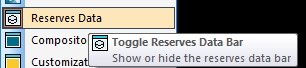
The Pit Data control bar is shown by default, but can be shown/hidden using the Home ribbon's Show | Reserves Data menu item:
The Pit Data control bar displays a summary view of the managed reserves data within your project.
This data is generated as part of The Reserves Workflow and is a convenient way of analyzing the current status of mining block reserves preparation. You can use it to:
- view if data has been generated for the basic workflow steps, for any pit, phase or bench
- see the status of each pit (i.e. does it have a topography, associated model and/or generated dependencies?)
- for each step in the Reserves Workflow, for each pit and phase, which data files have been generated
- see which data files are currently on display
- access the overlay properties dialog for any reserves managed data file and subsequently edit its visual formatting.
There are two grid indicators possible for any position on any grid:
 Data exists and is currently displayed in the
Task or any 3D
window.
Data exists and is currently displayed in the
Task or any 3D
window.
 Data exists but is not currently loaded/displayed
A grid-like arrangement is used to display information, split up into the following areas:
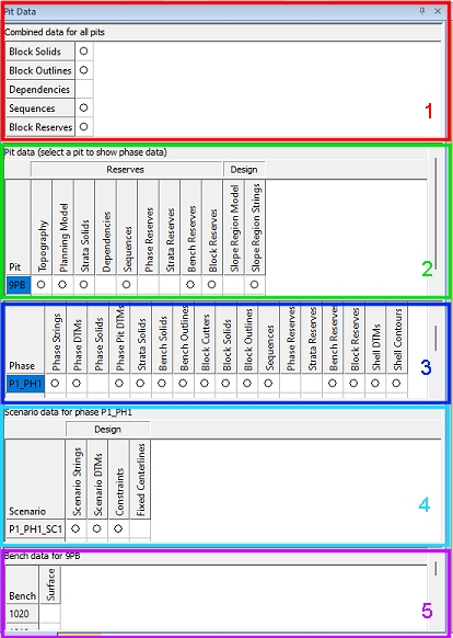
- Project data: shows,
for any defined pit, phase or bench, whether one or more data
files exists for the following data types:
- Block solids: mining blocks, as created by any of the available block generation routines (Auto by Bench, Auto All, Manual Outlines).
- Block Outlines: as above, but this represents the string files representing the outlines of each mining block.
- Dependencies: if a dependencies file exists for any pit, this box will contain an empty or filled circle. More...
- Sequences: if a block sequence file exists for any pit with the current project, you will see a circle here (filled or empty). More...
- Phase/Bench/Block Reserves: global (pit-wide) reserves can be displayed (in Table Editor) using the Block Reserves option. You can also review more granular reports at the Phase and Bench level, using the corresponding button.
- Pit data: shows, for
each pit that has been defined
for the current project, the status of the following data types
- Topography: indicates whether a topography file has been associated with the pit. More...
- Planning Model: indicates whether a planning model has been defined for the pit. More...
- Dependencies: indicates whether pit-level dependencies have been generated. More...
- Sequences: if mining blocks have been sequences as part of the reserves workflow, you can display, format, save or hide the associated dependency arrows here. More...
- Bench Reserves: indicates whether bench reserves have been generated. Enabling this type of item will display the Reserves report in Table Editor. More...
- Block Reserves: indicates whether phase reserves have been generated (normally at the same time as Bench Reserves). Enabling this type of item will display the Reserves report in Table Editor. More...
- Slope Region Model: indicates if a slope region model exists within the project database. If slope regions have been defined based on an attribute within the planning model, you can manage your slope model data here. More...
- Slope Region Strings: indicates if boundary strings have been used to define slope regions. More...
- Phase data: shows,
for each phase within each pit, the status of data types at key
stages of the Reserves Workflow.
Phase Strings Strings representing the external geometry of a pit phase and are an input to the Define DTMs managed task. These strings are used to create Pit DTM surfaces (see below). 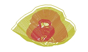
Phase DTMs Surfaces generated from the Phase Strings (above) as part of the Define DTMs task. These surfaces represent the external limits of each pit phase, and are used to create volumes - Phase Solids (see below). 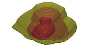
Phase Solids Solid volumes based on the previously created Phase DTMs. These are generated as part of the Create Solids managed task and will be subsequently spliced horizontally using the current Bench Definitions to form bench solids. 
Phase Pit DTMs Generated during the Create Solids managed task, these files describing how the topography would look after the current phase solid has been extracted from it. 
Strata Solids This data represents phase solids that have been subdivided by surfaces specified with the Define Strata task. This data is then generated using the Strata Solids task.
Once generated, these solids then carry the corresponding strata information through to the processed mining blocks (either manually or automatically generated) and are reported independently using the Reserves evaluation tasks and further on into operational scheduling.
Bench Solids Bench solids are volumes created by a subdivision of each Phase Solid according to the currently defined bench definitions. These are created by the Bench Solids managed task and will subsequently be 'cut' into mineable blocks for sequencing. 
Bench Outlines Outlines strings generated for each bench as part of the Bench Solids managed task. 
Block Cutters Open or closed string data that will be projected downwards in order to cut up each bench solid into mineable blocks.
This string data is either generated interactively or imported.
Block Solids Closed volumes resulting from the splicing of bench solids with cutter strings (Block Cutters - see above). This process is completed, and mining block volumes are generated, using either the Auto By Bench, Auto All or Manual Outlines managed tasks. Blocks will be colored according to their corresponding phase by default. 
Block Outlines Strings generated during block generation that describe the outline of each mining block. 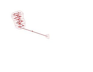
Sequences A data table describing the mineable sequence of each generated mining block. These are generated as part of the Sequence task and will honor any previously specified dependencies. 
Phase ReservesBench ReservesBlock Reserves Reserves table containing categorized grade/tonnage data. This will be either categorized according to the phase, bench or block. This is used as an input to the operational scheduling functions available on the Schedule ribbon. This data type is now a 3D geospatial table so cannot be viewed in 3D or Task windows. Instead, you can see the contents of a generated Reserves table by clicking the respective circle icon in the table. This will display the Reserves Table data using Table Editor. 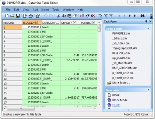
Constraints Strings used to constrain the shape of the generated pit. These can be any data, but are commonly a subset of the contour strings (see below) generated as part of automated pit design. 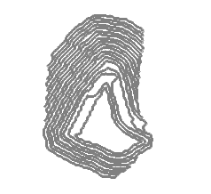
Shell DTMs Shell DTMs are generated by the Shell Contours task. These intermediate surfaces are used as a basis for ramp layout definition. 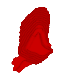
Shell Contours Contour strings, as generated by the Shell Contours managed task. This string data can be shown or hidden for each phase, and formatted independently by double-clicking any displayed (solid circle) item. 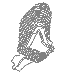
Fixed Centrelines Display all centreline strings for fixed roads, for the current project.
Fixed roads are created either using the Auto Pit Design or Auto Dump Design tasks

-
Scenario data: this section will update depending on the selection made in the Phase Data section, above. The following data can be displayed/hidden using the radio button controls in this area. Data for the selected scenario ID is listed per row:
-
Scenario Strings: if pit design strings have been calculated for the scenario, they can be hidden or displayed here.
-
Scenario DTMs: if auto pit design pit shells have been calculated for the scenario, they can be hidden or displayed here.
-
Constraints: any constraint strings associated with the pit design scenario can be toggled here.
-
Fixed Centrelines: if fixed roads were designed for the selected scenario, their centrelines can be toggled.
-
Bench data: if you have defined 3D surfaces for your bench data, this section of the control bar allows you to enable or hide the display of 1 or more bench surfaces. Find out more about bench definition options...
Pit Data Dynamic Controls
The Pit Data Control Bar is dynamic and will update automatically where data is added to or removed from the project. Similarly, where visibility of data changes, the table will update automatically.
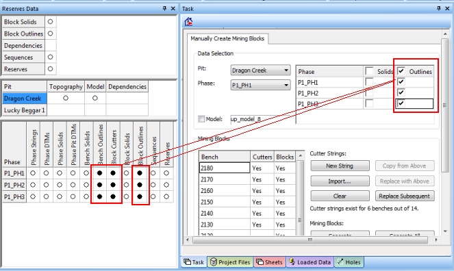
For example, if you are working with Manually Create Mining Blocks task and choose to show outlines for, say, 3 phases, the table will update to show Bench Outlines, Cutters and Block Outlines:
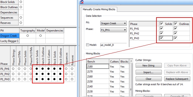
If the 3 phase solids are displayed, the table
updates again to show that bench and generated block solids are being
displayed:
Context-sensitive Menus
The Pit Data control bar
includes a context-sensitive menu for the various data types. The
contents of the menu will depend on whether an object is currently
displayed (solid circle) or not (empty circle).
Non-displayed Objects: right-click any object in the table to see the following options:
Show: display the selected item in the Task window for all 3D data types, or for Reserves data, open the corresponding file in the Table Editor. Reserves data will only be displayed that corresponds to the selected pit and phase.
Copy
to...: save a copy of the selected object to a physical Datamine file on disk, using a file browser.
Displayed Objects: right-click any object in the table to see the following options:
Hide: hide the displayed item in the Task window.
Format...: opens an object properties dialog to allow you to change an object(s) visual formatting. Note that this dialog is identical to the one shown if using the 3D window and Sheets control bar. More...
Save As...: only appears if the current object has not already been saved using the same mechanism. This option allows you to save the selected object to a location on disk as a single- or extended-precision file. More...
|
|
Related Topics |
|
|
The
Reserves Workflow
Open Pit Mine Design Define Benches Define Slopes Define Pit Regions Shell Contours Ramp Layout Auto Design Task |